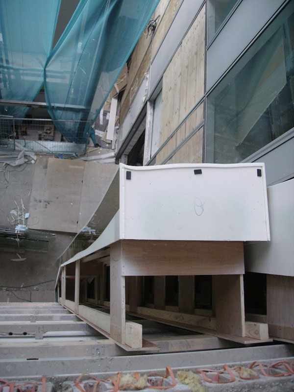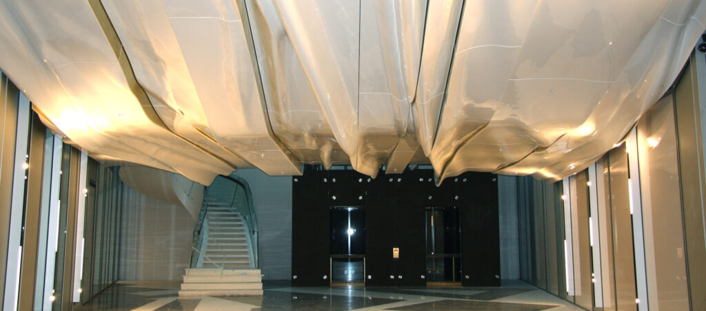
In 2007 Erick van Egeraat Architects (EEA) made a design for a covering of the auditorium inside the Mahler building that was built in Amsterdam. Again, because of the complex shape to be realised in combination with the requirements on fire behaviour the choice to use A1 was obvious.

In 2008 Poly Products has developed a method for realizing and mounting of the elements. Each element has been laminated with A1 in a mould. In the inner part of the element 36 mm plywood strips have been incorporated as mounting beams. While still in the mould, strips of 18 mm plywood strips were screwed to these beams. The plywood strips, 6 or 8 per element and extending from the back of the element were used later on for mounting the element in the building.
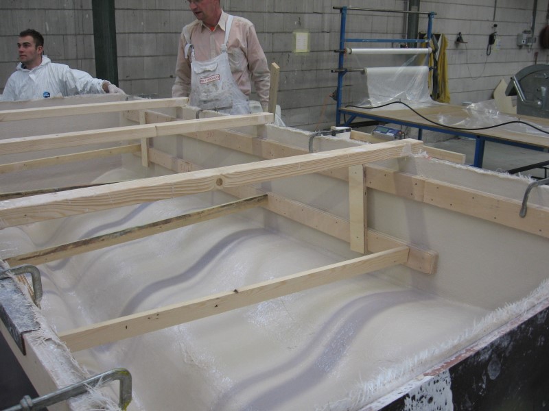
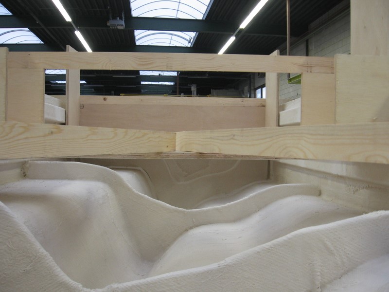
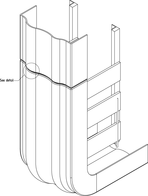
The principle of the mounting of an element to the building structure is based on the fixation of the protruding 18 mm plywood strips at the back of the element to wood beams that have been installed to the building structure, see figure below.

The 18 mm protruding plywood strips have a relatively high strength and stiffness in vertical direction in which direction they have to carry the weight of the element. In lateral direction these strips behave relatively flexible which makes the alignment with the adjacent elements relatively easy.
For the dilatation gap between two elements that are in line with each other in first instance it was designed to realize this by means of a joggle. However, this would involve additional inserts in each mould. Moreover, to obtain a situation that is nicely flush from one element to the other would become difficult. And there would be the risk of damaging the joggle during mounting of the element when the joggle of one element had to be fitted into the internal space of the neighbouring element. With the connection of two elements as depicted below it is illustrated how this has been solved with another detailing.
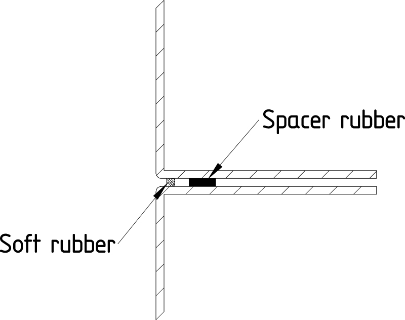
Instead of a joggle, both elements were provided with a flat head plane. On one of the elements spacer rubbers were stuck to provide the desired dilatation distance. Near the visible edge, a white, compressible rubber strip has been stuck at a fixed distance of the outer edges. The principle is depicted in the figure below.
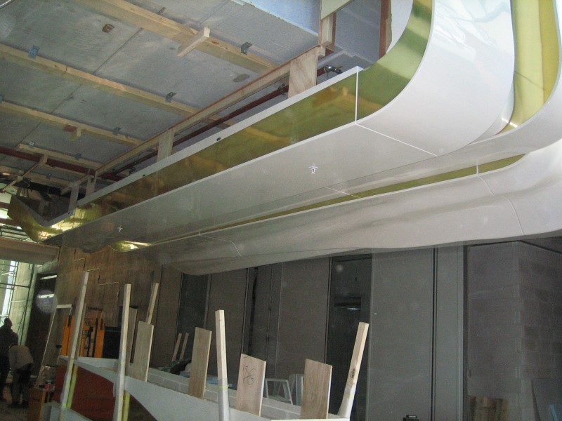
During mounting of an element it could be softly placed on the previous element that was provided with the spacer rubbers and the strip op white, soft rubber. This is shown in the photo below.