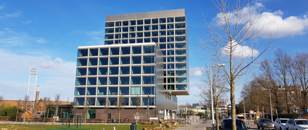
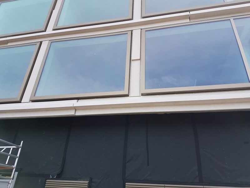
In 2017 Rijnboutt architects has designed the Fletcher Amsterdam Olympic Hotel. In the facade elements have been designed with a concrete look between the windows. These elements are oriented both horizontally and vertically.
The building company Van Wijnen Lelystad has investigated the possibility to use thin-walled profiles for these elements together with Poly Products. By using thin-walled profiles, a low weight can be realised that facilitates the mounting process and reduces the requirements on the anchoring of the elements to the building.

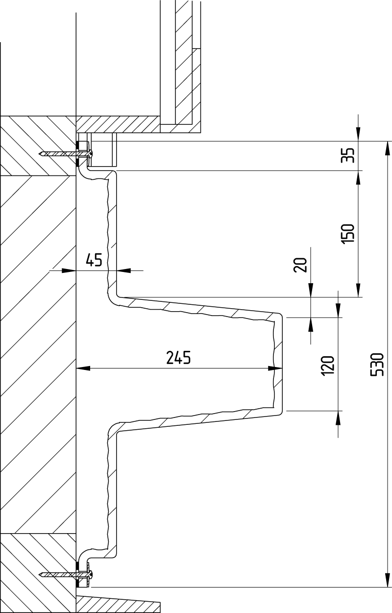
Of the horizontal elements different types have been produced. The type that was most critical in wind loading will be considered in the following. The figure shows the cross-section of this element and relevant dimensions.
For the structural evaluation specially the wind forces are important to evaluate. In the following this is described for the given profile.
Wind loading on the element
The maximum height for the elements is 47 meter above ground level. The building is located in a non-built environment in Amsterdam. According to Eurocode NEN-EN 1991-1-4 these parameters determine a design wind pressure of:
Pd = 1.34 kPa = 1340 Pa = 1340 N/m2
For wind suction, the so-called external pressure coefficient amounts to:
External pressure coefficient
(wind suction) = Cpe = -1.4
Because the wind loading is dynamical, the load factor is:
Load factor = Yf = 1.5
The projected area of one meter of the profile is:
Projected area of one meter profile = A = 0.53 m2
From this, the design force, Fd, for one meter of profile can be calculated:
Fd = pd · | Cpe | · γF · A = 1340 · 1.4 · 1.5 ·0.53 = 1491 N
Strength of connection to the building
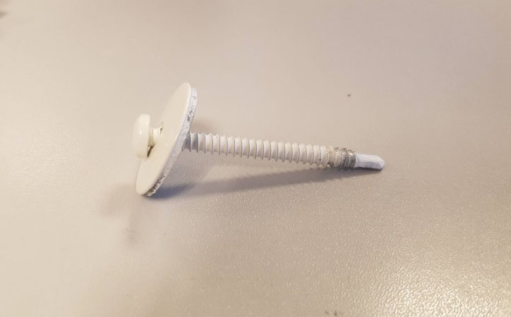
The strength of the connection of the profile to the building is determined by the method of connecting. A screw with a diameter of 5 mm and a shaft length of 60 mm is selected for this. For spreading the load, a washer is used with a diameter of 29 mm. Screw and washer are shown in the photo below.
The elements are mounted with these type of screws to rulers of spruce. With an effective depth of the screw in the spruce ruler of 29 mm, the pull-out strength is 1821 N (according to EN 1995 for wood structures). For this pull-out strength a material factor is to be used of γm = 2. Thus, the design pull-out strength of a screw,
Fpull is:
Fpull = 1821 / γm = 1821 / 2 = 911 N
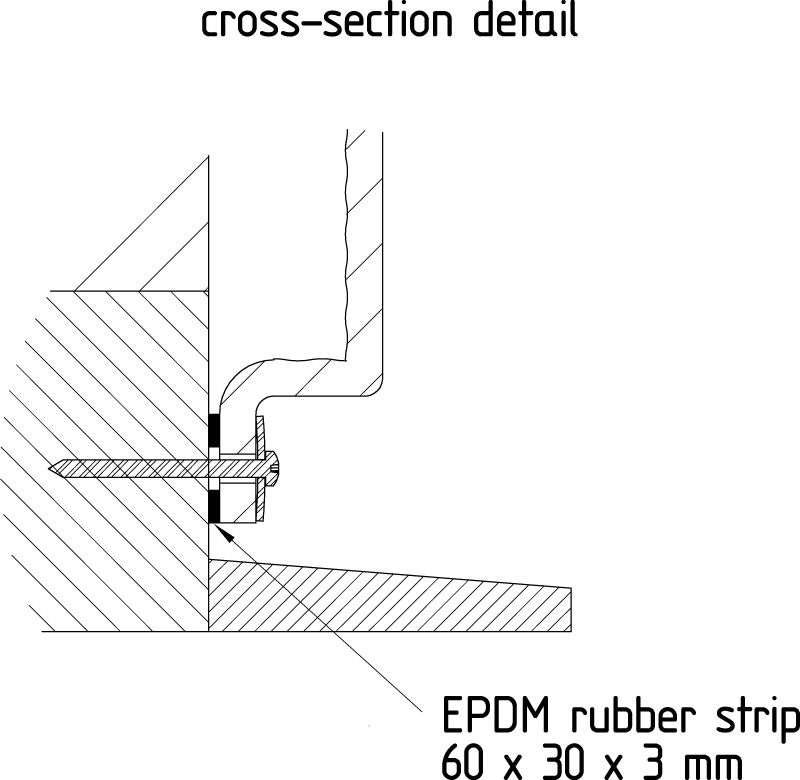
Another aspect to consider is the pull-through strength of the screw and washer through the A1 flange. In the figure below it is illustrated how the screw and washer can be pulled through.
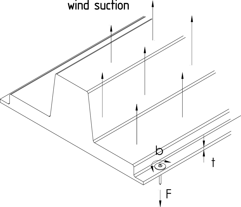
An interlaminar shear stress in the laminate with occur as a result of the force. The area of the fracture, Af , is determined by the length of the fracture, b ≈ 75 mm, and the thickness of the laminate, t = 5 mm. The shear stress distribution over the thickness will be parabolical and results in the following fracture force,Ff :
Ff = 2/3 · d · Af = 2/3 · 1.50 · 75 · 5 = 375 N
In this equation the design value for the interlaminar shear strength for A1, d , is derived from the table on page 11. In this parameter already material factors
are comprised. It is clear that the fracture force of pull through, Ff, is critical in the connection of the element to the building.
The screws are always placed in sets of two, each on one flange of the profile. When comparing the design load with the design strength of a set of two screws, the amount of screw sets per meter profile can be calculated:
Amount sets per meter = Fd / (2 Ff) = 1491 / (2·375) = 1.99
This means that one set of two screws is necessary for every 1/1.99 = 0.50 meter. Thus, along the flange the screws should therefore have a distance of 500 mm
maximum.
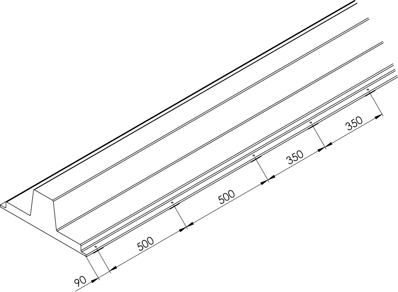
In the project the maximum distance of the screws is selected to be 500 mm. Moreover, the maximum distance of screws near the end of the profile is selected to be 90 mm. Because the lengths of the elements vary, sometimes the distance between two screws is less than 500 mm. A typical screw pattern in the project is illustrated.
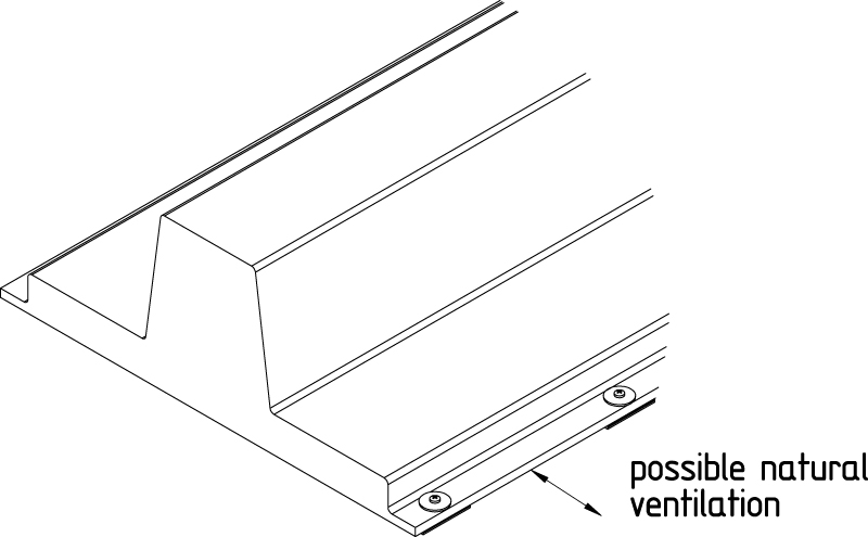
In order to avoid accumulation of moisture due to condensation, an opening is created between the element and the building structure.
These ventilation openings are realized by placing 3 mm EPDM-rubber strips between the element and the building during mounting.
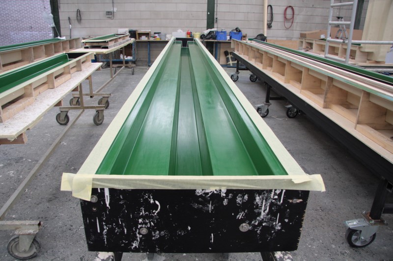
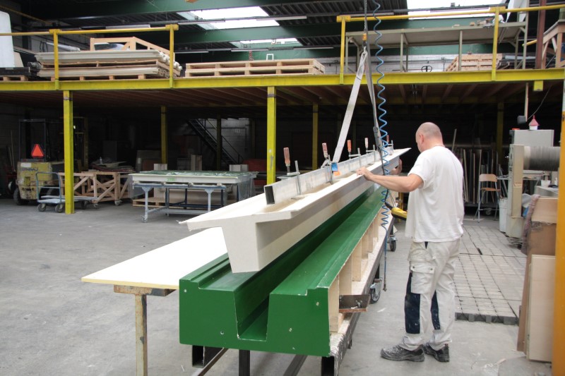
The elements have been produced from polyester moulds using hand lay-up. For stiffening of the element in width direction aluminum profiles have been incorporated in the back-side of the elements. These aluminum profiles also have been used to release the product from the mould and for further handling and transportation.