In Eurocode EN 1990 the generally accepted design method for structural parts is described. For the structural evaluation the incorporation of loads is described in Eurocode EN 1991.The incorporation of the material behaviour is only standardised for traditional materials like steel, concrete, wood, aluminum and masonry in Eurocodes EN 1992 to EN 1999. For A1 there is no description in the Eurocodes how to deal with this material specifically. However, EN 1990 describes a methodology how to determine material properties for the structural evaluation of a design by doing tests. For this, Annex D of this Eurocode is used: Annex D (informative) Design assisted by testing.
When following the assessment of a material property via the characteristic value (D7.2) for a certain material property X, a design value Xd can be determined from tests data in the following manner:
Xd = ηc · Xk(n) / γm = ηc · mX · { 1 – kn · VX } / γm
In this formula the parameters represent the following:
Xd = design value of material property X
ηc = conversion factor
Xk(n) = 5% characteristic value measured values
γm = material factor
mX = mean value of measured values
kn = factor for 5% characteristic value
VX = coefficient of variation ( = sX / mX )
sX = standard deviation of measured values
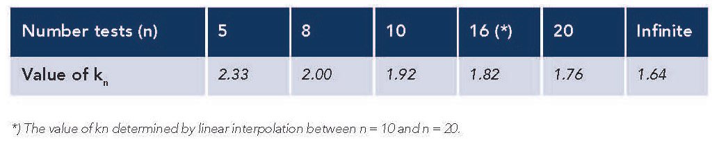
The value of kn depends on the number of test samples that have been tested. These values are listed in Table D1 of the standard. In the following table some of these values are given assuming that the coefficient of variation (Vx) is unknown beforehand.
Two factors need more explanation: the conversion factor, ηc , and the material factor, γm . The conversion factor is material specific and incorporates external effects on the material:
1) temperature, 2) moisture, 3) creep and 4) fatigue.
1. Conversion factor for temperature
As is customary for composites the conversion factor for temperature is set to 1 (no additional effect) in case the design temperature remains below 40 ºC under the glass transition temperature (Tg) of the material (see also CUR-96). Thus:
ηc,T = 1 for design temperature Td < Tg – 40
For A1 the glass transition temperature,Tg, is determined
to be 155 ºC and therefore it is recommended to allow for design temperatures up till 115 ºC. In that case the conversion factor for temperature is 1.
2. Conversion factor for moisture
In case of A1 the scope for structural applications is limited to relatively dry environments. However, A1 is known to be sensitive for variations in moisture. A test series has been performed to compare mechanical performance of A1 laminates that have been stored at 50 % RH with laminates that have been stored at 86 % RH until equilibrium (both at room temperature). These results are listed in Appendix B in the A1 Design Guide .
For A1 it has been found that strength and stiffness will be lowered when stored at 86 % RH as compared to storage at 50 % RH. However, there is a difference in effect between 0º tested properties and 90º tested properties. This is evaluated in Appendix B and results in the following conversion factors for moisture.
ηc,M = 0.75 For 0º properties
ηc,M = 0.60 For 90º properties
3. Conversion factor for creep
In case of A1 the scope for structural applications is
limited to situations with no significant permanent
loading. Allowed loadings are non-permanent, e.g.
wind loading. It must be checked that permanent
loading because of weight is negligible. In these cases
no creep effects are to be expected and the conversion
factor for creep is set to 1:
ηc,C = 1
4. Conversion factor for fatigue
For composites it is customary to use the following conversion factor in case of cyclic (fatigue) loading (see also CUR-96):
ηc,F = 0.9
Thus, for the design for applications where the temperature remains under 115 °C, that are relatively dry and impose no significant permanent loading on the structure, the conversion factor can be calculated from the above conversion factors to be:
ηc = ηc,T · ηc,M · ηc,C · ηc,F = 1 · 0.75 · 1 · 0.9 = 0.68
For 0º properties and for direction-independent (interlaminar) properties
ηc = ηc,T · ηc,M · ηc,C · ηc,F = 1 · 0.60 · 1 · 0.9 = 0.54
For 90º properties
In the same manner the material factor is evaluated. This factor consists of a part that takes into account the possible uncertainties in the determination of the property. For the determination of the property from tests this factor is:
γM1 = 1.15 (when determined from tests)
When the property is determined from theoretical models or literature references this factor would be 1.35 (more uncertainty than with testing). But this is not the case here.
For the variations in the manufacturing method it is assumed that the product is made by means of hand lay-up. Furthermore, it is assumed that the product is fully cured. It then depends on the expected coefficient of variation what material factor is to be used. Because it is clear from the tests that the coefficient of variation is generally larger than 10 %, the values from the CUR-96 are adopted for the higher coefficient of variation. Then, with this manufacturing method the factor is (see also CUR-96, Table 2.2):
γM2 = 1.0 For stiffness
γM2 = 1.5 For strength and global stability (buckling)
γM2 = 2.0 For local stability (wrinkling)
Combining the two factors, the material factor becomes:
γm = γM1 · γM2 = 1.15 · 1.0 = 1.15 (stiffness)
γm = γM1 · γM2 = 1.15 · 1.5 = 1.73 (strength, gl. stability)
γm = γM1 · γM2 = 1.15 · 2.0 = 2.30 (local stability)
Taking above parameters in consideration and using the data from a test series of n tests (with accompanying
value for kn), the formula for the design property becomes:
Xd = (ηc / γm) · Xk(n)
= (ηc / γm) · mX · { 1 – kn · VX }
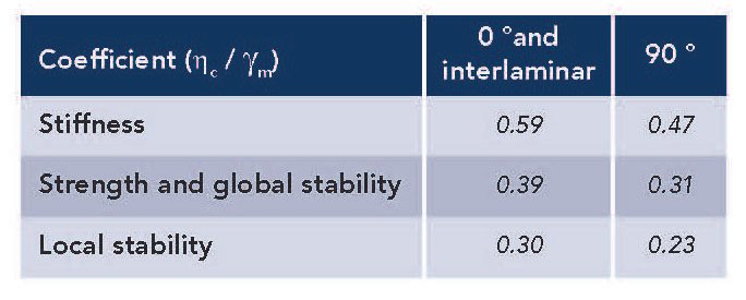
Because the conversion factor depends on the direction
of the property considered (0º and 90º) and the material factor depends on the type of mechanical analysis considered (stiffness, strength, global stability and local stability), first a table is made of the coefficient (ηc / γm).
The design method is specifically worked out for
the following laminate properties of a reinforced A1
composite product:
*)Interlaminar strengths do not depend on reinforcement direction.
Above properties have been tested on fully cured laminates (at least seven days after production, stored in a dry and ventilated room). Before testing the samples have been conditioned to laboratory conditions (23 °C and 50 % RH). The test results are described in Appendix B of the A1 Design Guide. The properties are based on the testing of a series of specimens, where the number of specimens (n) depends on the type of test. In the following table the results of the tests are summarized. Both mean value (mx) and coefficient of variation (Vx) are given.
Using the design method the test results are used to determine the design parameters that are summarized in the table below. For the E-modulus in tension, only 7 measurements could be used, thus kn = 2.08 is used in this case (*).