Acrylic One (A1) is a two-component resin. The components are a powder component based on calcium sulfate (CaSO4) and an acrylate-based liquid. After mixing of these components the resin can be processed to make products. The resin is water-based and does not generate the emission of VOC’s (Volatile Organic Solvents). Typically the time the resin is liquid after mixing of components (‘potlife’) is 20 minutes but can be lengthened by using a retarder or can be shortened by using an accelerator. Additional filler (e.g. sand) can be added to the mixture as well. In the liquid state the resin can be processed in different ways: casting, application on a substrate, spraying and laminating together with reinforcement in a mould. Specially in combination with a glass fibre reinforcement, thin-walled products can be made with a complex shape and with a low weight. Because of the short curing time, short production times are possible. This enables an efficient production process.
Besides the advantages of A1 of making complex-shaped, light-weight products in an efficient manner, a very important property of A1 is the performance in reaction to fire. This performance has been reported to be B – s1, d0 according to the European standard EN 13501 (report Efectis of 2006) and even A2 – s1, d0 in case the A1 compound is filled with 25% sand (report Efectis of 2017). This is a superior fire performance when compared with composite products that are based on traditional synthetic resins or when compared with wood-based materials.
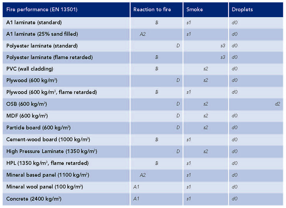
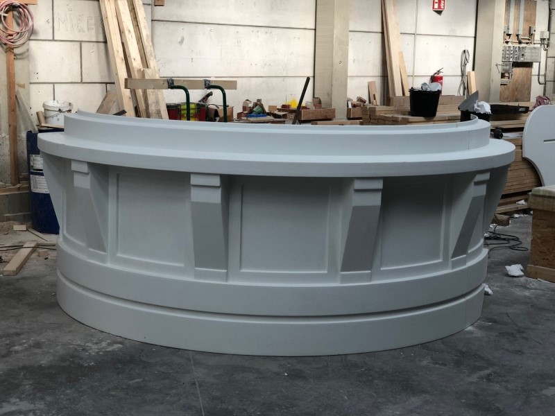
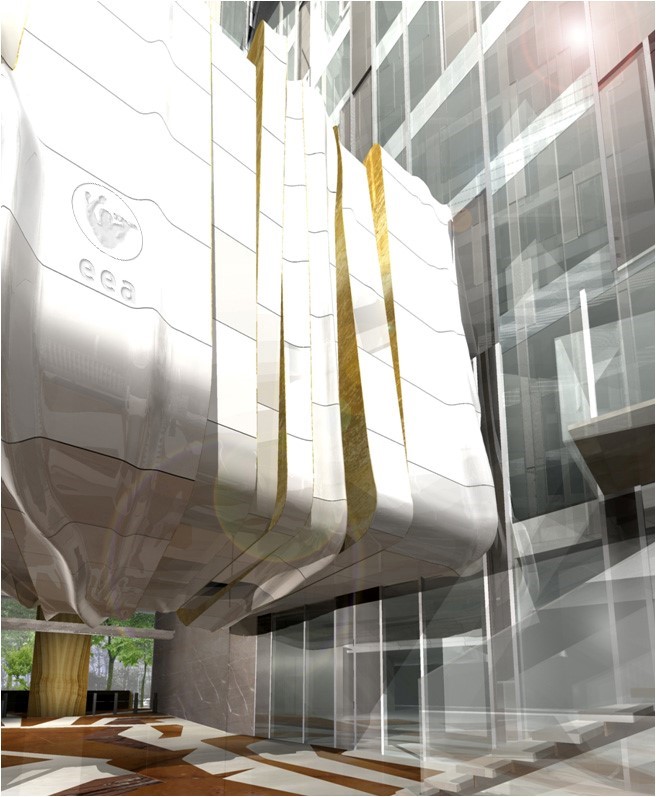
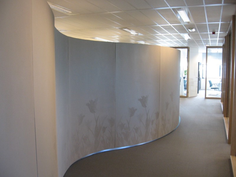
Both the good reaction to fire (A2) and the low smoke production during fire (s1) are superior to that of e.g. polyester-based laminates. This makes it possible that products made with A1 can be applied in interior projects and in critical facade applications. Typical interior projects that were possible by using A1 with respect to fire performance are the ‘Tulip walls’ and the ‘Auditorium’. These projects both were realized by Poly Products, see photo’s below.
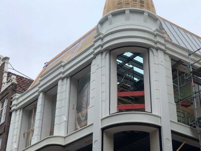
Typical exterior projects that were possibly by using A1 with respect to fire performance are the façade elements for La Place in Amsterdam and the façade elements of the apartment building in Nijmegen. These projects both were realized by BeConcrete, For La Place in Amsterdam 35 façade-elements have been produced using A1. The requirements on fire performance in combination with freedom of shape and low weight resulted in the choice for A1.
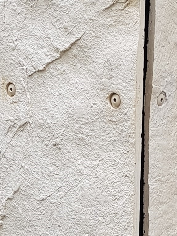
In the Rentmeesterkwartier in Nijmegen an apartment building had to be renovated. In total 1800 m2 of façade elements were installed that fulfill the fire requirements. A special surface texture was requested. Moreover, the elements should have a maximum weight of 15 kg/m2 and must be easy to install. This lead to the selection of A1 from which panels have been manufactured. The panels were screwed directly to rules on the building. Screws were coated in the same colour as the panel and a recess in the surface at the screw location made the screw less visible.
In the following table a comparison is made of laminates based on A1 and several other materials. These materials include glass reinforced laminates based on a standard polyester resin and a polyester resin with the highest possible frame-retardancy (FR), polyester concrete and wood-based panels.
As described in the introduction, A1 is typically a composite that excels in fire behaviour. However, mechanical performance and moisture resistance are on a significantly lower level than composites based on glass reinforced polyester or glass reinforced epoxy. To illustrate this, in the following table properties of a glass reinforced A1-laminate are compared with a glass mat reinforced polyester (UP) laminate (indicative values).

*) Determined by bending test in direction with highest degree of reinforcement.
Moreover, composites built up with A1 show a significant water uptake in conditions with a high moisture content. In these conditions the mechanical performance is further reduced and creep deformation under permanent loading is accelerated. However, when dry again the original mechanical performance is regained. These considerations lead to the following field of application of composite built up with A1:
Relatively dry applications:
– no permanent moisture contact
– no permanent high humidity
Avoiding creep deformations:
– no permanent loading
To quantify the term ‘no permanent moisture contact / high humidity’ the time scale in which moisture uptake by A1 must be considered. When A1 is brought in contact with moisture (e.g. by immersion) or with a high relative humidity, the process of moisture uptake takes one to several weeks, depending on the thickness of the A1 product. Therefore, the exposition to moisture or high humidity of A1 should be limited to several days maximum. With all above considerations in mind, the field of application of composites built up with A1 can be described as follows:
Indoor applications:
– dry areas (average RH under 75%)
Outdoor applications:
– façade applications
– art objects (dry and ventilated)
With respect to outdoor applications some further remarks have to be made. In case of facade applications the A1 products should not make direct contact with the ground to avoid moisture uptake. To quantify this, the A1 products in a façade should have a minimum vertical distance from the ground of 20 mm. In general for outside applications horizontal planes and locations where rain and snow can collect should be avoided.
For outside applications the durability of A1 has been investigated by TNO in 2008 and by SHR Timber Research in 2016. In outside applications the use of the specific sealer for A1 is important for maintaining the surface quality. However, for the structural performance the sealer has been found to have no influence. Moreover, it is possible to use an anti-graffiti coating.
An A1 structure is built up by laminating reinforcement together with the A1 resin in a mould. In order to avoid dry spots in the product surface, the laminating must be started by the application of a non-reinforced resin layer of 0.5 to 1.5 mm thickness (0.8 to 2.4 kg per m2). The thickness of this layer depends on the application method and the use of additives in the resin, e.g. sand.
After a short time of gelation of this layer (see production instructions of A1) the reinforcement layers are applied together with the resin. For each triaxial glass fabric layer of 160 g/m2 about 1.0 to 1.7 kg of resin per m2 is needed. Each such a layer will build up a thickness of 0.7 to 1.1 mm.

The general instructions for A1 are that a minimum of 2 reinforcement layers should be used in a laminate. However, for structural applications of A1 (for which this design guide applies) a minimum of 3 reinforcement layers should be used. There is no maximum amount of reinforcement layers. A1 does generate some exothermic heat during curing but not to an extent that it may cause material degradation or fire risks. During curing of thick laminates a maximum exothermic peak temperature has been found of only 50°C. However, when thick laminates are required, the use of core materials (e.g. foam or wood) should be considered.
The triaxial reinforcement has glass bundles in the weft direction of the structure (called 0° direction) and at angles of +45° and – 45° with the weft direction. There is no reinforcement oriented in the warp direction (called 90° direction).
As can be seen from the photographs, the fibre bundles are oriented in weft direction (horizontal direction in the photographs, called 0° direction) and in directions +45° and -45° with the weft direction. In the warp direction (vertical direction in the photographs, called 90° direction) there are no glass fibre bundles oriented. However, the stitch-yarns are oriented in the warp direction.
For determining the design properties of A1 composites that are reinforced with triaxial reinforcement the orientation of the reinforcement is important. In case all reinforcement layers are stacked in the laminate with the same orientation, there will be directions that are reinforced with glass fibre bundles but there will be also a direction (the 90° direction) in which there are no reinforcement bundles oriented.
It may be expected that the direction in which there are no fibres oriented performs less strong and less stiff than de reinforced directions (0°, +45° and -45° directions). Depending on the requirements and on the quality control possibilities different approaches of the orientation of the reinforcement layers are possible:
Controlled orientation:
– All reinforcements same orientation
– Alternating orientation of reinforcements
Uncontrolled orientation (random reinforcement orientation)
In this design guide for two extreme situations the design properties are determined. These properties are determined by testing laminates with 5 reinforcement layers in which the layers are oriented in a controlled manner with all reinforcements having the same orientation. Mechanical testing has been performed both on specimens oriented in the 0° direction (reinforced) and in the 90° direction (non-reinforced).
The design values obtained by the tests in 0° direction give the highest possible performance that can be obtained by controlled orientation in production where all reinforcements have the same direction and are oriented in the direction in which the mechanical load acts. The design values obtained by the tests in 90° direction give the lowest possible performance and is a safe design level for cases where an alternating reinforcement orientation is used or when the orientation is uncontrolled (random). The following figure shows schematically the directions of reinforcement in a laminate with controlled orientation of the reinforcements and the reinforcement all having the same orientation.

For the design with reinforced A1 composite products the following laminate properties for quasi-static loading are important:
*) Interlaminar strengths do not depend on reinforcement direction.
Above properties have been tested by SHR. The test results are described in Appendix B and refer to SHR test report 18.0387. Using the design method, the test results are used to determine the design parameters. This procedure is described in Appendix A. The summary of the design parameters is given in the table below. These are valid for applications within the scope described in this report.
In case of possible vibrations of the structure (e.g. resonance that is induced by wind), it is recommended to analyse the eigenfrequencies of the structure. For this analysis it is recommended to use both the E-modulus for bending for stiffness calculations (1363 MPa / 477 MPa) and the E-modulus for bending for global stability calculations (901 MPa / 315 MPa).
A specific remark is made on the linear thermal expansion of A1 laminates. The coefficient of linear thermal expansion of the material has been determined by TNO to be 5·10-6 -/°C (see TNO report of 2008). This value is significantly lower than of other materials. This results in relatively small dilation provisions necessary. In the following table values of the coefficient of linear thermal expansion are given.


For designing with A1 attention has to be paid to several aspects of design details. In the following, design details and mounting methods are given. Also limits are given to what is thought to be functional for a good design. It does not necessarily mean that when the recommendations of this design guide are not followed the design is not good. What is written in this guide is to the opinion of ACS and the author a good way for designing with reinforced A1 products.
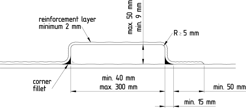
Many design details are determined by the fact that A1 for structural parts is always processed with reinforcement layers (triaxial glass fabric) that is built up together with the resin into a laminate in a mould. Because the application of the reinforcement layers in a mould, the radius of the mould surface should have a minimum radius. When the radius in a product becomes too small either part of an outer product edge will be non-reinforced (and therefore weak) or an inner product edge will suffer from badly impregnated reinforcement. Therefore, as a general rule product edges should have a radius R:
R >= 5 mm
It must be remarked that the making of products with A1 with edges with a smaller radius or even sharp edges is not difficult from production point of view but the structural performance (strength) of such edges will possibly be low.
Furthermore, when products are made with flat parts the free span of these parts (p) should not be too large. This depends on the thickness of the laminate. Also the total length between two supports (s) should not be too large. For parts that are only supported at one side the length of the free span (q) is limited. However, an extra flange allows for a larger free span. Schematic illustrations on the next page show the meaning of the parameters p, q and s. In the table below the maximum values for the parameters are given in relation to the laminate thickness. The values are given for three thicknesses that will cover a range of thicknesses that will be often used for laminates made with A1.


For flanges, the minimum and maximum length depends on the thickness. Also for multiple flanges minimum and maximum lengths are dependent on the laminate thickness. In all cases the minimum radius of the corner at the mould side is 5 mm. The following figures and tables give the numbers.


Joggles are often used to fit a product into a neighbouring element. The space between the joggle and the adjacent element can be kept open (air) to allow for undisturbed play (dilatation) between the elements. But also the space can be used to glue the two elements together. The thickness of this space should be kept to a minimum in case of an open space (air) in order that surface irregularities will not hinder the free movement. On the contrary, for a glued space the thickness of the space should be limited to a maximum to avoid a too thick adhesive layer.


Stiffeners can be realised during the hand lay-up process by incorporating profiles in the laminate. Such a profile then acts as a core material in a local sandwich build up. Suitable materials that can be used as a core material for stiffeners are plywood, solid wood, aluminium profiles, EPS foam and PET foam. When a core material is used, the outside surface of it should be pre-wetted with resin during laminating to ensure good adhesion with the reinforced layers.
It is recommended to use wood-based core materials only for A1 products in indoor applications. Moreover, when wood-based materials are used as a core material, the top side of the resulting structure can also be used for connecting other parts by screwing.
The following pictures show methods to incorporate profiles as a core in a laminate.


Field of application
A1 laminate with reinforcement
Controlled lay-up: design values for 0° direction can be used (for the reinforced direction)
Other lay-up (alternating, random): design values for 90° direction to be used (can be used always, in any direction)
The coefficient of linear thermal expansion reinforced A1 laminates is 5·10-6 -/°C .
Design details
